SYSTEM Components for the Homemade AC/DC Generator System
- Gas (or Propane) powered engine
- Direct drive shaft couplers
- AC generator head, 3600 RPM
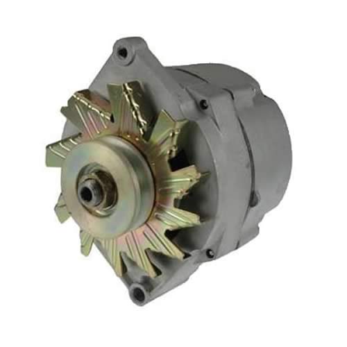
- GM alternator, 12 volt or 24 volt
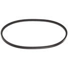
- Industrial V Belt
- Pulley (similar to shown)
- Horizontal Shaft Alternator bracket (Epicenter's own!)
SUBSYSTEM Components for the Homemade AC/DC Generator System
Main Components in the AC subsection
The project could stop here if DC is not required*
Components that Add DC charging capability
Mount the alternator to the engine!
Add this bracket — makes it easy! Add cables for the final touch.


* Please Note: TheEpicenter.com does not sell AC Generator Heads.
Generator Questions
Q: So why would I ever want to build my own generator when I can just buy one ready to go?
A: That's a darn good question!
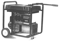 In many cases its better to just lay down the cash and buy a quality AC generator like this Generac model, but in other cases there is really no way to have everything you want without making it yourself. That is if you need lots of DC charging and also sine wave AC power as well.
Then again, it might not cost as much as you might think to build your ideal system if you already have one of the key components.
You might be one of those DIY-ers who might have a spare engine sitting around and could use it to drive a generator head without needing to purchase an expensive and dedicated AC generator system. In some cases it could be less expensive to purchase the generator head and reuse an engine from something else that you no longer have a need for, or only need for a few months each year.
A good example would be a person who has a pressure washer sitting around that has a large engine, possibly a high quality and expensive one like a Honda. In that case you could remove the pump assembly from your washer and attach a generator head when needed in the winter, and in the spring you could remove the generator head and reattach the pressure washer pump assembly.
A better case could be made for building a multipurpose power generation system because it is not something that you can currently buy. In this application you might need to charge of bank of batteries as an example at the same time as having some AC power available. In this application the same engine can direct drive a generator head while belt driving an alternator for DC charging purposes.
In general, when someone wants to charge a bank of batteries there's often excess horsepower available which could be used to run an AC generator head at the same time. Or on the other hand, you might need AC power to make repairs around the house with power tools, or you might need to run the microwave, refrigerator or something, and would like to charge your batteries at the same time.
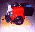
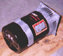
 Shown here at the left is a prototype of a project I'm experimenting with for my own use.
The AC generator head is direct coupled to the Tecumseh 8 HP motor, and has a belt driven 12 volt alternator mounted to our Horizontal generator bracket which is attached to the motor. To get the full rated output of 6,000 W peak from the generator head, this particular motor is under powered. To develop the full rated output power from this head, the engine should really be a 10 HP model like the HM100, or better yet an 11 HP model for a bit more headroom. Of course running an alternator exclusively on this engine is an example of overkill but the combination of the lower output of AC at the same time as DC is available makes for a fairly efficient use of fuel and resources.
For my application, I don't require more than 2500 watts of AC power which would normally require about a 5 HP engine. The remaining 3 horse power can be devoted to the DC charging subsystem using the attached alternator.
Here is another view where you can see the direct drive and the belt drive components.
 Let's take a look at what's really required to make this generator head produce AC power for specific output current levels.
For full power, an 11 HP motor is specified by the manufacturer but other motors could be used if you do not violate the general rules outlined below. Trying to draw more power than shown below using an under rated engine horsepower rating will result in the generator producing an AC voltage lower than the specified output. In some cases this could cause a "brown out" condition which could result in electrical damage to the devices being powered. Special precautions should be taken to ensure that the example horsepower ratings and output power or levels below are not violated.
| AC generator output | Engine size required (for example purpose) |
| 6000W peak, 5000W continuous (full rated AC output, no DC) | 11 Horse power |
| 5000W peak, 4000W continuous | 8 Horse power |
| 3000W peak, 2500W continuous | 5 Horse power |
So, if you are using an 8 HP motor with this AC generator head and can insure you never will use more than say 2500W of AC power, then there is enough horse power left to be able to belt drive a 12 volt alternator running at say 40 amps (14.4 volts x 40 amps = 576 Watts) with some head room when belt driven off the same shaft.
Although the manufacturer specifically states that to develop the full rated output an engine size equivalent to eleven horsepower is required, smaller versions of this generator head produce lower continuous ratings shown in the table and require less horsepower. We have extrapolated the data shown from the specifications for the smaller generator heads, and although the larger 6000W peak head has more mass in the rotor, we would realistically expect that it doesn't require that much additional power to spin the rotor especially since sealed ball bearings are used on both ends of the head.
I guess what I'm trying to say is that if you can guarantee that you would never try to pull too much AC from the generator head, then even a small engine will not bog down and there would be extra horsepower available for other uses like running an alternator as shown in the prototype.
So, let's discuss some of the issues...
Typical Gas engines rate their horse power at 3600 RPM.
If the motor is used at speeds below that rating, the engine does not develop full rated output torque and horse power.
However, running an engine at a lower RPM increases fuel efficiency and decreases wear and tear so there are always trade offs.
 You should also note that these small engines output shaft rotates in counter clock wise direction as viewed from the output shaft side of the motor. This is something that will come up again!
Because most engines are rated at 3600 RPM, you will note that many generator heads are also designed to be rotated at 3600 RPM.
If you attempt to run the AC generator head a speeds below the rated RPM of 3600 in this case, the AC output voltage will not be 120 volts, but will be a lower value. Some equipment you intend to power may be more forgiving about the lower voltage, some equipment might be damaged, so it is critical that you spin the generator at the correct RPM. More discussion on setting the RPM of the engine and generator head can be found in the next section.
You will also want to note that the generator heads shaft needs to rotate in a clockwise direction as viewed from the shaft side of the generator head. So, place the shafts facing each other and guess what? Both the motor and the generator head rotate in the correct directions. This allows for direct driving the generator head by using a shaft coupler.
Now, let's talk about Connecting the Motor to the Generator Head
Q: How do you direct drive a generator head with an engine?
A: Direct drive shaft coupler assembly.
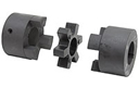
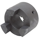 To connect the output shaft of a motor to a generator head input shaft (or anything else), a special shaft coupler is required. Basically, three pieces are needed.
Select a coupler half that is the correct size to fit the motor shaft (or driving shaft size), then select a coupler half that is the correct size for the generator head (or Driven shaft size).
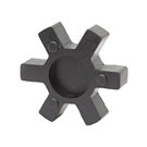 Then the two shaft couplers are joined using what is called a spider.
Notice that the shaft couplers each have 3 fingers and the spider has 6 slots. The three fingers from the motor side fit into three of the spider slots, and the three fingers from the generator side coupler fit into the other three slots on the spider. This coupler assembly allows for several degrees of misalignment between the two shafts and protect the bearings from seeing side loads that would result from misalignment.
These couplers are available in a bunch of sizes. Several sizes are available on our L-095 Couplers & Inserts page here @ TheEpicenter.com.
Q: When you're building your own AC generator using a gas engine and an AC generator head, how do you set up the combination so that the system produces the correct output voltage, and turns the generator head at the correct speed?
A: There are two approaches that can be taken:
 Measure the AC voltage to adjust the engine RPM.
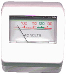
This AC volt meter plugs directly into any AC outlet and displays the measured voltage without the need to use a hand held DVM and jam probes into an AC outlet. The meter features a built-in AC plug on the back side.
Voltages within the standard 115 to 125 volts range are highlighted in green indicating acceptable voltage parameters. Voltages out side of those ranges are indicated in red. This meter provides an easy to read indication of the generator output voltage.
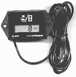 Measure the engine RPM with an inductive Tachometer, and also know when to change the oil! This device allows you to monitor and set the engine rpm such that it rotates at the specified RPM required by the generator head. This is an RPM (revolutions per minute) meter or tachometer. It inductively connects to the spark plug wire and senses the rate at which the spark plug fires over a given time period. The resultant measurement is displayed in revolutions per minute. The engine rpm can then be adjusted until the specified RPM of the generator head is achieved. If the RPM is adjusted to the manufacturers specification for the generator head, the rated output of the generator would then be 120/240 volts depending on the construction and specifications of the AC generator head.
The unit shown also keeps a running total of engine usage and display the number of hours and minutes the engine has operated. While the engine produce a Spark, the RPM is displayed. Once the engine stops running the total time the engine has operated in terms of hours and minutes is displayed. One thing to note about this Tac is that the hour meter can not be reset. However the cumulative run time displayed is extremely useful in deciding when you need to perform regular maintenance such as oil changes.
Engines that don't turn at 3600 RPM
Q: What if I have an engine that doesn't turn at 3600 RPM? Can a generator head like this be used somehow?
A: Yes! But it's a bit more complicated.
This generator head is designed with dual ball bearings to allow belt drive applications.
In this configuration, the generator bearings see a high side load and not all generator heads are built with the required bearings to handle this side load. However, the generator head we use is designed to handle the job.
Here is how you would figure out what size pulleys to use: Ratio of RPM = Ratio of pulley size
In more detail:
Engine RPM / Generator RPM = Generator pulley size / Engine Pulley size.
So, knowing the generator needs to rotate at 3600 RPM, next define what speed the engine needs to run at. This ratio will determine the ratio of pulleys required.
Let's say for example that the engine is a Diesel that needs to run at 1800 RPM for full rated torque. Then plug the values into the equation and you get:
1800 RPM / 3600 RPM = 1/2 = Generator pulley size / Engine Pulley size.
So, what ever size pulley is selected for the generator, the engine pulley size must be 2 times that size.
The selection of pulley size is also complicated by the fact that not all pulleys are available in all shaft diameters. And, the outside diameter of pulley sizes is not always the effective diameter when using one style of belt as opposed to using another style of belt. Since belts of different styles ride higher or lower in the groove of the pulley, the effective diameter of the pulley can change if another type of belt is used, but the effect is seen on both pulleys so the ratio of pulley size is still applicable for most applications.
If you are unable to define a pair of pulleys that are standard, available and give you the exact ratio, then there are three choices:
1. You could use what is called a "variable pitch" pulley, which is a pulley that allows the width of the groove to be adjusted. They are very specialized and a bit expensive. Since the belt is a fixed width, adjusting the width of the "variable pitch" pulley causes the belt to ride higher or lower in the groove, thus effectively adjusting the "pitch diameter" of the pulley. I mention this only for academic reasons (so some smart ass out there doesn't beat me to the punch) because the other choices below are simpler.
2. Use the pair that give you the least ratio error, and then adjust the throttle of the engine to compensate. This method can not be performed by simply using a tachometer without doing some computations to correct the tac reading. A better choice would be to use a volt meter and adjust the throttle until 120 volts output from the generator is achieved.
3. You could use an intermediate shaft and a combination of two pulley ratios. This option is only needed in EXTREME cases where the ratio is such that no combinations come close, or you don't have access to pulleys that fit one of your shafts. I'm not going to discuss this much as it gets a bit complicated, but there is an example of an intermediate shaft being used below.
We put together the table below to help you find pulley sizes that are considered standard in the industry. We don't stock all these sizes but can special order one for you if you can't find one locally that fits your need. The cells marked with "X" indicate that a pulley is available in the combination of shaft and diameter. Cells that are blank (or black depending on your browser) indicate that a pulley is not typically available in that combination of shaft size and diameter.
Notice that the "pulley size" shown below is the outside diameter. The actual pitch diameter depends on what belt is used. For example if an "A" style belt is used, they ride down in the groove such that you can subtract 0.25" from the size shown.
| Pulley size | Shaft size | ||||
| 1/2 inch | 5/8 inch | 3/4 inch | 7/8 inch | 1 inch | |
| 1.75 | X | X | - | - | - |
| 2.00 | X | X | X | - | - |
| 2.20 | X | X | X | - | - |
| 2.50 | X | X | X | X | - |
| 2.80 | X | X | X | X | - |
| 3.05 | - | X | - | X | - |
| 3.45 | X | X | X | X | - |
| 3.75 | X | X | X | X | X |
| 3.95 | X | X | X | X | X |
| 4.25 | - | - | - | X | - |
| 4.45 | X | X | X | X | X |
| 4.75 | - | - | - | X | - |
| 4.95 | X | X | X | X | X |
| 5.25 | - | - | - | X | - |
| 5.45 | X | X | X | X | X |
| 5.75 | - | - | - | X | - |
| 5.93 | - | X | X | X | X |
| 6.25 | - | - | - | X | - |
| 6.93 | - | X | X | X | X |
| 7.93 | - | X | X | X | X |
| 8.93 | - | X | X | X | X |
| 9.93 | - | - | X | X | X |
| 10.93 | - | - | X | X | X |
| 11.93 | - | - | - | X | X |
| 13.25 | - | - | - | - | X |
| 14.16 | - | - | - | X | X |
Here is a practical example of using intermediate shaft and dual pulley arrangement
 In the example shown, I was attempting to convert an induction motor into a generator (that's something that is outlined in the booklet "alternator secrets"). The motor on the left is a one hoarse power motor which turns at 3,450 rpm when powered with 120 VAC and the motor to the right is an induction motor that runs normally at 1725 rpm.
For testing purposes, I wanted to use the motor on the left to spin the motor on the right at the correct speed so but I could test the conversion of the induction motor, and verify the output voltage. However, the motor on the right had a very small pulley which was frozen on the shaft and there was no way to remove it. My original plan was to remove the pulley and put a multi step pulley on both motors so I could achieve the gear reduction from a 3450 rpm driving motor through one belt to the 1725 rpm motor. That would require having a pulley one-half the size on the faster motor as the pulley size on the slower motor. Like I said, I couldn't get the pulley off the motor on the right.
So, what I ended up doing was to drive the motor on the right through an intermediate shaft which had a multi step pulley on it. The two pulleys were of equal size so the speed on the intermediate shaft would be exactly the same as the speed of the motor on the right side. Next I placed a multi step pulley on the motor which normally turns at 3,450 rpm (the left motor) and belt drove that to a pulley groove on the intermediate shaft that was twice the size. So for each revolution of the motor on the left, the intermediate shaft would rotate 1/2 of a revolution which would cause the gear reduction from the left motor to the right motor to be exactly one-half. Thus, when the motor on the left rotated at 3450 rpm the motor on the right would rotate at 1725 rpm.
Let's pretend that I could have installed the correct size pulley on both motors in the first place. And lets pretend the motor on the left is a gas engine and the motor on the right is a generator head. Then, the situation is best shown with an equation:
Ratio of RPM = Ratio of pulley size
In more detail: Engine RPM / Generator RPM = Generator pulley size / Engine Pulley size.
Knowing that I needed the engine to run at 3450 rpm and the generator to run at 1725 rpm, then... 3450 RPM / 1725 RPM = 2
Then say I've got a 2" pulley that fits the engine side, that means that the generator side needs to be twice as large, or 4".
Let's Take Another Belt Drive, for example
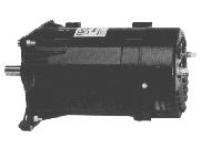
 Here is an old Onan AC generator head. This beast needs to rotate at 1800 rpm to deliver 120/240 volts AC. Most of the small gasoline engines you'll find have their rated horsepower output specified at 3600 rpm. Knowing that the engine rpm must be at 3600 to develop full horsepower and also knowing that the Onan generator head needs to rotated 1800 rpm it becomes obvious that we can't just direct drive this particular generator with a gasoline engine. Some form of speed reduction is required.
For this application the same formula applies and is shown below:
Engine RPM / Generator RPM = Generator pulley size / Engine Pulley size.
Knowing that we would need the engine to run at 3600 RPM, and the generator to run at 1800 rpm, then... 3600 RPM / 1800 RPM = 2
Since I had a 3" pulley already for the engine, I needed to determine the pulley size that would be correct or the generator shaft. Again, from the above equation:
2 = Generator pulley size / 3"
So, the Generator pulley size would need to be 6".
Wiring it up
The advantage of using the AC generator head in this project is that the AC connectors are pre wired to connectors on the back of the head. There are two connectors, one for 120 volt and one for 220 volt, each having two outlets.
- One 120 volt Duplex (two outlets) 20A Receptacle, 5-20R
- One 240 volt Duplex (two outlets) 15A Receptacle, 6-15R
The DC section can be wired several ways depending on what type of alternator is selected.
 The wiring depends on which alternator you choose. All three alternator types are shown.
Do not wire the alternator unless you are sure about what type you are using. If you make a mistake in the selection of the alternator or wiring diagram you run a very high risk of damaging your battery, electronic devices, or worse yet causing personal injury!
Consult a parts professional for additional information!
This article is intended for educational purposes only. No guarantees are expressed or implied as to the accuracy of information presented here! Consult with an automotive wiring expert before attempting to carry out any wiring.
One final note: If you are using an alternator that requires an external switch, you will need to turn off the switch prior to attempting to start the generator. Once the motor is running, the switch can be set to the on position.
Special parts used in many of our power related tips are available here at TheEpicenter.com!
- Parts needed for the Horizontal Shaft Generator Project
- Parts needed for the Vertical Shaft Generator Project
- Parts needed for the Direct Drive Generator Project